For the new rear axle, as it is also succinctly called at the university, it was not necessary to “reinvent the wheel”, but at least the hubless drive wheel with a huge wheel bearing is a design innovation. In which the drive axle is shifted off-centre and connected to an outer rim via a spur gear.
The nice thing about starting a completely new design is that you have all the design freedom at your disposal. However, it is also a great challenge, because it is both complicated and time-consuming to take into account all the requirements and properties of the Traction‑X rim to be designed. After all, manufacturing, assembly and handling in the customer’s hands should be taken into account right from the start, as should the technical requirements of the individual components, such as the maximum sliding speeds or the forces that can be endured. Not to mention the availability of affordable components that meet these requirements without making the business case impossible, i.e. making the product unsellably expensive. It is all the more pleasant to be able to fall back on good preliminary work on the demonstrator and patent drawings, despite all the constructive freedom.
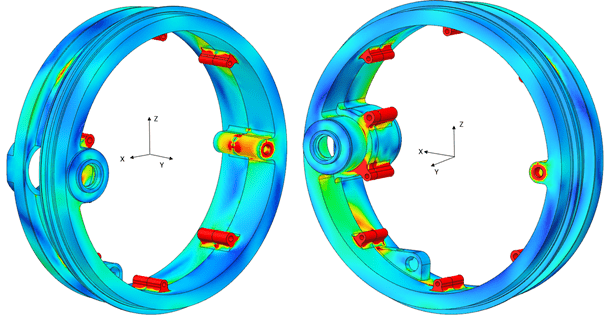
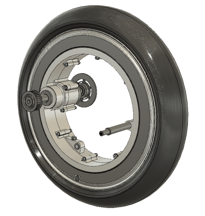
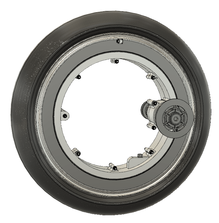
Thus, in the course of the last eight months and in the combination of two individual project works and a bachelor thesis, a complete and functional CAD model of patent variant 1 (Drive-Train Swing-Wheel) was created, which can be seen in Fig. 1. In addition, several finite element analyses determined that the Traction‑X rim would withstand the anticipated loads with a high degree of certainty. At the beginning, it quickly became clear that the scope and complexity of the requirements or tasks were too much for just one Bachelor’s thesis (mine) and one individual project thesis (Jonas Burwinkel). Therefore, we separated the areas of requirements analysis and preliminary design into a second individual project work, which I carried out. At the same time, I was able to use the time to familiarise myself with the operation of Fusion360. This was followed in my bachelor thesis by the detailed design of the entire rim with components that are actually available on the market and the meshing to the finite element model, starting from the CAD model of my Traction‑X design. In order to obtain realistic results for the following calculation of the static stresses, the calculation parameters used had to be determined in the best possible way. Figure 2 shows the graphical evaluation of one of the calculated load cases. It can be seen that the stresses in the current design are low (high safety) and thus material or weight of the rim can be reduced.
Parallel to my work, my fellow student at the TH Köln, Jonas Burwinkel, took care of the design and calculation of the gear shaft in his project work.
At the beginning of the project, it was important to understand the complex and not entirely trivial statics of the rim in order to be able to calculate the loads of driving on the individual components. However, since the driving operation of a scooter is anything but static, we came up with the following substitute model: for the highest starting loads, we imagined an imminent traffic light start, a “cavalier start” (a somewhat dusty expression). The driver therefore gives “full throttle” or commands the electric motor to full starting torque by turning the knob on the right, but remains on the front brake until the traffic light turns green. This load case was mentally superimposed with further dynamic increases due to driving through potholes. Since our system behaves very well and linearly, this is permissible. However, the free-body diagrams of the complex transmission, which do not appear in this way or in a similar way in any statics textbook in the world, were a problem.
With the operating loads and the requirements for the service life of our Traction‑X drive, it was then possible, in consultation with a well-known bearing manufacturer, to select suitable bearings for the gearbox and to design the gearing and the drive shaft. The large wheel bearing turned out to be much more complex. Knowing that in the second patent variant this would be replaced by a race on three rollers, the preliminary choice fell on a so-called thin-ring bearing. Although this fulfils the technical requirements, it would be far too expensive for use on Traction‑X. Here, the difference between a mass market for affordable scooters and the market for construction machinery or military vehicles, where such bearings are also used but where costs play a minor role or no role at all, becomes clear. However, this expensive bearing has already been replaced in the current design version by a so-called wire-race bearing, which is much cheaper.
In order to be able to transmit high power, the rim should be provided with oil bath lubrication. This requires very large radial shaft sealing rings that seal the circumferential rim bed against the standing inner rims. These sealing rings are additionally protected from the outside with caps. Since we do not want to introduce hub caps for two-wheelers, of course, we have agreed on the term “wheel ring”. These clamp in the grooves that are also used to attach the glued balancing adhesive weights. All in all, this idea met with a very positive response, also because the good designer should familiarise himself with the habits of his customers, some of whom clean their vehicles with a high-pressure cleaner out of convenience, but do not want to risk damaging their rear wheel drive.
To increase the cleanliness of the oil, metal debris is collected by a magnet on the filler plug. To make the oil change particularly user-friendly, the oil drain plug is easily accessible on the outside of the rim bed. These design details were also met with praise, as they simplify maintenance and increase service life.
Motivated by the solution of each challenge and by the exchange with the team members during the bi-weekly meetings, it is a pleasure to work on Traction‑X. The good teamwork is remarkable, especially since all communication is purely digital. I would like to take this opportunity to thank all the people involved in the Traction‑X project.
I am looking forward to accompanying the further development of the project and to seeing the results of the next works. The project leader added that he is also indebted and that he is looking forward to the time after Corona because he really wants to catch up on the opportunity to pat some shoulders (with gloves on) and shake hands.

Vergleichsspannungen aus Finite-Elemente-Berechnung 
Traction-X-System mit Brems- und Riemenscheiben 
Traction-X-System rechtsseitig in Fahrtrichtung

thanks for share about GREAT ADVANCES IN DESIGN
You are welcome.
Thanks for your interest.
Kind greetings to Indonesia.